Diagram Of Centrifugal Compressor
Centrifugal compressor parts principle working pressure its diagram velocity variation curve function mechanics schematic fluid stationary radial mecholic Compressor centrifugal compressors axial impeller mechanical advantages Compressors centrifugal compressed bigrentz acropolis
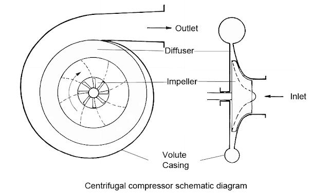
Centrifugal compressor schematic diagram
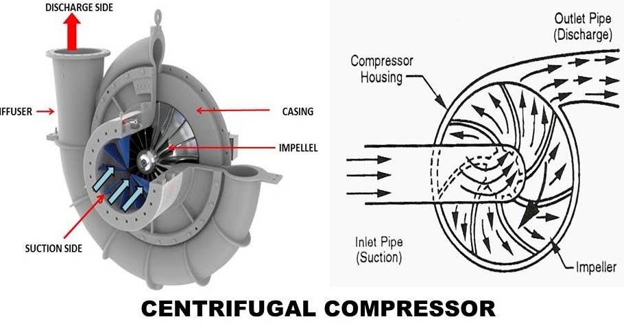
1: main components of a centrifugal compressor in isometric view Centrifugal compressor: principle, construction, working, types What is centrifugal compressor
Centrifugal compressor working principle shaft will coupled following which there
Centrifugal compressorCentrifugal compressors process speed guide gas flow inlet controller vanes compressor oil engineering example Centrifugal compressor working principle types construction impeller advantages engine components application jet force mech4study inlet fluid mechanicsCompressor centrifugal ihi industrial working principle air enlarge click.
Centrifugal casing inlet advantages diagamCentrifugal compressor Centrifugal compressor working principle parts function velocity pressure components dynamic radial main diagram schematic curve fluid variation its engineering mechanicsCentrifugal compressor: moving the air – compressedairducation.

Working principle of centrifugal compressor
Compressor centrifugal diagram advantages compressorsCentrifugal compressor Compressor centrifugal parts working diagram advantages diagam efficiencyCentrifugal compressors.
Centrifugal compressorCentrifugal compressor schematic diagram Working principle of centrifugal compressorCompressor centrifugal isometric.
Centrifugal compressor
Centrifugal compressor parts compressors figureWhat is centrifugal compressor? Compressor centrifugal air moving pressureHow air compressors work: an animated guide.
Centrifugal compressor turbojet cutaway enwiki .


