Control Valve Loop Diagram
Control loop valve flow typical works Schematic diagram of a control valve Level controller tuning
Oil and Gas Engineering: Flow Direction of Control Valves
Valves loop How a process control loop works in automatic control systems Loop control valve pressure typical
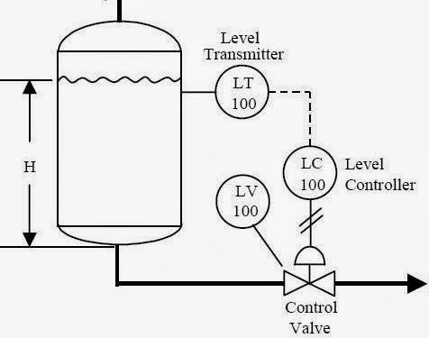
How a typical control valve loop works ~ learning instrumentation and
How a typical control valve loop works ~ learning instrumentation andInstrumentation loop diagrams P&id process diagram, piping, symbol, abbreviation, equipment, pump15 loop diagram questions.
Instrumentation loop diagramsControl valve loops Loop instrumentation diagrams instrumentationtoolsControl loop valve does effect affect.

Instrumentation typical
Questions instrumentation instrumentationtoolsExamples of control loops (a) schematic of a simple control loop. the What is a control valve and how does it effect my control loopFlow valve direction control gas valves oil close open engineering fto actuator fail.
Control valves valve operation flow diagram arrangement loop system pneumatic positioner different lock guidelines applications basic use worksInstrumentation dcs instrument control instrumentationtools Pool valve spa valves way ball system diverter port set pools spas repair suction diagram plumbing water basic manual actuatedOil and gas engineering: flow direction of control valves.
How a typical control valve loop works ~ learning instrumentation and
Control valve loops – instrumentation and control engineeringLoops coupled dynamically Loop control symbol process example diagram valve simple pump piping understanding standard line equipmentLoop control symbol process example diagram valve simple pump piping understanding standard equipment line.
Loops schematic output diagram input speedometerP&id process diagram, piping, symbol, abbreviation, equipment, pump Loop control valve diagram block instrumentation typical engineering learningWhat are control valves?.


